By Grayson Evans, KJ7UM, Copyright 2020
INTRODUCTION
The 6BN6 Gated Beam thermatron is unique. It’s constructed like no other thermatron I have ever come across in radio electronics. It was the only tube of its type ever built1 but fortunately it is still readily available at low cost. For some time I have wanted to explore it’s application potential as a mixer/product detector. This article is the result of my investigation of the tube primarily as a product detector mixer. You’re going to like this thermatron.
BACKGROUND
The 6BN6 was developed at Zenith Radio Corporation in Chicago, around 1949 by Dr. Robert Adler and commercialized by Allen Haase at General Electric. It was designed to combine the functions of a limiter, discriminator and audio voltage amplifier in FM and intercarrier television receivers. The tube design and operation was initially described in two papers by Adler2 and Haase3 which I will talk more about shortly.
The original purpose of the 6BN6 development was to produce a thermatron which would have inherent amplitude limiting characteristics and fit into an FM detector circuit requiring a minimum number of components. But it has another life.
STRUCTURE
The 6BN6 is unique from several standpoints. The electron beam in this tube takes the form of a sheet beam of varying cross sections and current densities as it travels from cathode to plate. There are no focusing or intensity adjustment as are found in most circuits in which electron beam thermatrons are used. It is divided into three sections (see diagram below): a cathode compartment which originates the sheet beam, the limiter grid and accelerator grid compartment, and the quadrature grid and anode compartment. The beam creating accelerator shields the cathode from the electrostatic fields of the control grids and serves to make the cathode current independent of control electrode potentials. It has two control grids: the limiter grid, which operates similar to a conventional control grid, and the quadrature grid, which acts like a second independent control grid. Part of the reason for separating the compartments was to minimize any space charge and capacitive coupling between grid elements.
The pin-out on the GE data sheet is drawn like a conventional pentode, but that is misleading. It is definitely not a pentode. The diagrams below are more representative of the actual internal structure. The one on the right is taken from the GE application note and shows the compartmentalized structure, and the one on the left is my interpretation that I use in schematic diagrams.

How It Works
To quote from Adler and Haase, “…it was our objective to design a tube which would have two control elements each having essentially a step function transfer characteristic in order to realize efficient circuit iteration at low input levels.
Together, these features make possible switching the plate current between cutoff and its limiting value with low input signals to the receiver. In response to a grid potential which changes from negative to positive, the plate current rises abruptly from zero to a sharply defined maximum level. No further change occurs in the plate current no matter how strongly positive the grid may go.”

The grid transfer curves are not like a convention triode or pentode (see figure above). They are reminiscent of a diode transfer curve, but not quite. The limiter grid has a very linear super-sharp-cutoff region which, I believe, gives the tube its high conversion gain. When the limiter grid is biased near the mid-point of its control characteristic, it passes the beam during positive half-cycles of the applied signal and cuts it off during negative half-cycles. The quadrature grid operates in a similar way; if it swings negative, the plate current is cut off. During a positive swing, the plate current rises sharply to a plate maximum level.
The two grids act as gates which open and close periodically, depending on the phase relationship of the two grid signals. The beam can reach the plate only when both gates are open; plate current starts with the opening of the second gate and ends with the closing of the first. The mixing principle is similar to that of a diode balanced mixer only with gain.
For mixer operation, the IF signal should be applied to the limiter grid in a conventional way. The optimum bias (about -1 to -2 volts) corresponds to the start of the steep part of the grid curve and in operation this bias should remain fixed. The BFO signal is applied to the quadrature grid, its amplitude large enough to control the plate current from cutoff to plate limit. The quadrature grid should be returned to ground through a low DC resistance, preferably an inductor.
EARLIEST USES
The earliest amateur radio reference to the 6BN6 is a QST article by W9BIY and W9IHT in May, 1960 QST, Some New Ideas in a Ham-Band Receiver. They used the 6BN6 as a product detector and were very happy with the results. “We believe that the product detector [of this receiver] is a significant improvement over many of the circuits which have been published…A glance at the 6BN6 curves show that grid 1 [limiter grid] is almost perfectly linear over a range of 2Vpp (0.7V rms), while outside this range the tube limits sharply…With 3-4 volts of BFO injection on grid 3, the 6BN6 has a conversion gain of 50.”
As far as I can determine, the next amateur radio use did not occur until Spring of 2005 with the design of the “Retro 40” receiver in SPRAT by Dr. Andrew Smith, G4OEP. I mentioned this receiver in a previous article on the 6JH8 mixer. He also read about the tube as a product detector in the 1960 QST article and wanted to try it out. This is from an email correspondence with me a few years ago. “I was thrilled to bits when I realized what this tube can do, and was also pleased that this use of it is a thoroughly theoretical application of the technique for which the tube is designed. The point is that the original use as a FM detector is a clear application of the quadrature-detector principle. In this idea the incoming IF signal is applied to a tuned circuit which naturally, near resonance, carries a current whose phase is nominally 90 deg relative to the excitation, but whose phase varies with frequency so that when multiplied with the direct IF, the result contains a dc component (or average value) whose magnitude varies with frequency [see data sheet]. So anything which can be used as a FM quadrature detector must function as (must actually be) a product detector. This theoretical idea pleased me greatly. Of course in the Retro the quadrature signal is replaced by the BFO, so the multiplying mixer acts as an SSB detector, and it does its job very well indeed.”
TESTING
In the few articles where I could find the thermatron being used as a product detector, there was little consistency in how the circuitry around the thermatron was designed. The GE data sheet recommendations are for use as a quadrature FM detector in TVs. However there are a few values and notes that give some guidance, so I decided the best option was to build a test circuit so I could vary all the operating parameters while measuring the results. My test circuit is shown below. I varied the plate and accelerator voltage, cathode bias, and input signal levels to produce the best gain, lowest distortion, and lowest unwanted mixer products. The thermatron performs a mixing function over a wide range of operating voltages, and in fact, operates better at low voltage. It will work amazingly well down to a plate/accelerator voltage of 25/20V.


The data sheet recommends a cathode bias of 1-2 volts to put the limiter grid at the transfer curve sweet spot. My best results were at 1.5V. Since the plate current remains almost constant regardless of the input signal levels (due to the structure of the tube), this never needs adjusting once set.
The schematic shows the values that I found produced the cleanest audio output with very high conversion gain. You should adjust the values of the plate and accelerator dropping resistors to get between 50 to 75 volts on the plate and 40 to 60 volts on the accelerator. I made a series of tests to simulate the tube in a typical product detector. The signal applied to the limiter grid (pin 2) was an RF sine-wave from a signal generator. Amplitude was varied about a typical last IF level from 0.01V up to 0.5Vpp unmodulated.
The signal applied to the quadrature grid (pin 6) was an RF sign-wave simulating a BFO with a level of 1 to 5Vpp. The frequency of the two signals was varied from 450 kHz up to 10 mHz separated by 1-2 kHz so that the difference in frequency would output an audio signal in the 1-2 kHz range. The mixer circuit output was fed into scope and spectrum analyzer to monitor the combination of output signals. The two tables below are the results. The second table shows the levels of the unwanted mixer product outputs. The photo below shows the levels on the spectrum analyzer.
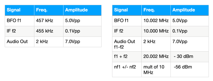

Note that 0.1V IF to 7.0V audio out is a 37 dB conversion gain! That is pretty amazing. The audio output dropped off to 0.5 Vpp when the IF level dropped below about 0.05 Vpp. I ran the test at an IF of 1 MHz, 5 MHz, and 10 MHz, with 2 kHz spacing and the results were exactly the same. There is no performance drop off up to about 50 MHz.
The photo below is of the audio output shown at the plate of the 6BN6 with no filtering. This is the “raw” mixer output. It is visually difficult to detect any distortion. The BFO and IF signal show up as “fuzzyness” on the 2 kHz signal.

I did notice an annoying 0.2V 60Hz AC filament voltage coupling to the output signal. probably coupled from the filament to the cathode. I had to power the filament with a DC source to get rid of it. It is probably due to loss of the insulation on the filament wires over time.
Audio Output Filtering
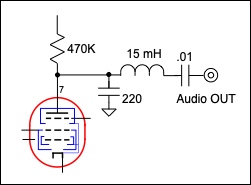
Since the unwanted mixing products are low to begin with, very little filtering on the audio output is required. In the original QST article and in Andy’s Retro article, the only filtering was a small value capacitor to ground. I experimented with various combination of low-pass filters, but found there wasn’t much difference. I settled on the circuit shown below which filters out everything above about 5 KHz. I assumed the audio would go directly to one end of a 500K volume control. You probably don’t need the inductor.
Applications
The primary application in ham radio is obviously as a product detector. I am about to “drop it in” to a 455 kHz IF strip I have on the bench to find out how it performs with SSB. The high audio output of this mixer means I only need one stage of audio amplification to drive a speaker. It may not have enough enough sensitivity to work as a front-end mixer, but I plan on prototyping a direct-conversion receiver with a 7788 RF amp and band-pass front-end. Normally the 7788 has too much gain to use as a front-end RF amp, but since the 6BN6 is essentially overload proof, it might work. I will let you know in a future article.
NOTES and REFERENCES
1. GE did make another version, the 6SK6, in 1965 that has slightly different curves and is designed to operate at higher voltages. I have never seen it used.
2. The 6BN6 Gated Beam Tube, Part 1. The Laboratory Prototype and Its Circuit Applications, Dr. Robert Adler, Proceedings of the National Electronics Conference, Sept. 1949
3. The 6BN6 Gated Beam Tube, Part 2. The Commercial Realization of the 6BN6, Allen Haase, Ibid.
