(Took me a long time to post this, sorry. I wrote it in 2023 summer I think. Posted today Feb 17, 2024)
I’ve been experimenting with several homebrew thermatron VFO designs lately. Typically, my VFO design is for a single band, single conversion receiver to mix with the incoming RF and cover 250 to 350 KHz depending on the band. The part that consistently gives me headaches is always the tuning mechanism. I have several boxes filled with nice variable capacitors, The challenge is to gear down the tuning capacitor appropriately to cover the desired tuning range and improvise some kind of dial mechanism that accurately represents the received frequency (VFO freq +/- IF). I really need a simpler approach.
While noodling the problem, I remembered a bag of several varactor diodes in my stash of capacitors. I’ve played with varactor diodes in the past but mostly forgotten about them as a reliable variable capacitor. Can a cheap varactor diode actually be used to construct a stable VFO that accommodates the frequency range needed at upper HF frequencies?
Varactor Refresher
Varactors diodes (sometimes called epicap diodes or varicaps) are voltage controlled capacitors. All diodes exhibit a small capacitance when they are reverse biased, but the varactor is specifically constructed to change its capacitance by a known amount depending on the amount of reverse voltage. Varactors are operated in a reverse-biased state, so no DC current flows through the device. The amount of reverse bias controls the thickness of the diode depletion zone and therefore the varactor’s junction capacitance; more voltage, less C (Figure 1). However, varactors are inherently non-linear; it takes more and more reverse voltage to decrease the diode capacitance by the same amount. Notice that the capacitance scale is linear while the voltage scale is logarithmic—standard for varactors.

Figure 1. Capacitance vs Reverse voltage graph for the MV209
Varactor diodes are available in two configurations: a single diode such as the MV209 and a pair of back-to-back diodes in a single package like the BB104. The single diode is typically used in a circuit as in Figure 2, in series with another capacitor to isolate the DC control voltage from the tuned circuit. The dual diode has the advantage of incorporating two identical back-to-back diodes to provide the isolation.
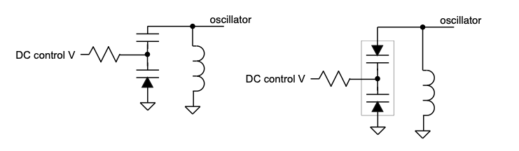
Figure 2. Two configurations of varactor diodes. Single (two terminal), left, and back-to-back (three terminal), right.
Since no significant DC current flows in the varactor, the value of the resistor connecting its cathode back to a DC control voltage can be in the megohm range. In very high-Q tuned circuits, a choke is used instead of the resistor to increase the source impedance of the control voltage so as not to load the tuned circuit and decrease its Q.
Common Varactor Usage.
Varactor diodes have been used here and there in ham radio equipment since the early 1960’s. A typical use is to remotely change the operating frequency of a filter such as a notch filter. This allows the frequency tuning device to be located someplace on the front panel while the circuit is elsewhere in the chassis. Varactors are also used in inexpensive AM or FM radios to eliminate the cost of a mechanical variable capacitor for tuning. The tuning dial is connected to a potentiometer that varies the voltage across the varactor. However, I can only remember one use as the main tuning cap in a VFO, Jay Rusgrove’s WA1LNQ, 1976 QST article, The Herring-Aid Five. He actually used back-to-back common switching diodes.
My Design
Building a VFO with a varactor instead of the traditional variable capacitor would have several advantages:
• It eliminate the mechanical variable cap.
• The varactor is very small and can be placed close to the tuned circuit
• The control mechanism can be a potentiometer mounted anywhere
• The varactor has a high Q
• It has a very small temperature coefficient (0.14 pF for 24° C temp change)
However, on the disadvantage side, it is very sensitive to voltage variations and noise (avg. 4pF/V), and it is non-linear.
To test the concept I built a prototype VFO as part of a 20M prototype front-end (Figure 3). It uses my favorite Hartley circuit (Figure 3) with a MV209 varactor as the main tuning capacitor. I used a MV209 simply because I had it and it has a convenient tuning range for the VFO frequency of 13.545 to 13.845 MHz. This will generate a 455 KHz IF.

Figure 3. Schematic of the VFO
Looking at the tuning characteristic chart (Figure 1), a 10p to 37p tuning range would mean a tuning voltage of about 2.0V to 10.0V, so I would need a source of very stable low voltage. Early testing with the circuit proved that the varactor is very sensitive to the source voltage so I added a Liner LT1236 precision voltage regulator to supply a very stable 10V source voltage to a 100K 10-turn pot, RF isolated with the 500uH choke. The pot supplies the variable voltage to the varactor to tune the oscillator.
To get the 10-37p tuning range of the varactor to cover the tuned circuit capacitive tuning range, I relied on Robert Weaver’s tuning capacitor calculator (see Notes). You give it the frequency range you want to cover, the inductor value, the tuning capacitor (in this case the varactor) tuning range and it will spit out Cp and Ct (see schematic). It will also print you a tuning range chart showing how linear the tuning range is. Very cool.
Once the prototype circuit was built (Figure 5 and 6), the tuning range was a bit off due to the usual stray C and L and component variations. I found the voltage needed to span 13.545 to 13.845 was about 9.48 to 1.72 volts. That is the reason for the 3.9K and 10K resistor on the top and bottom of the tuning pot. These allow the full 10 turns of the pot to cover the 300KHz tuning range. These probably should be small trimmers to make it easier to adjust. However, due to the non-linearity of the varactor, one turn covers 60 KHz at the low end of the band, down to 17 KHz at the upper end. I need a way to linearize the tuning better. One idea is to split the band into two tuning bands by switching in different capacitors. The other idea, which I will try next, is to use a varactor with a larger capacitance (MV2301) and operate it over a smaller more linear region of its capacitance curve.
Construction
I build everything, including power supplies, on copper-clad board cut to size. The prototype VFO (see Figure 5) is built on a 4 x 5 inch double sided copper-clad board with glued-on solder pads, cut to fit the small aluminum box. The mixer circuit was also built on a 6 x 2.75” copper clad board mounted behind the VFO. Both the VFO and mixer board are mounted on a piece of ½” plywood. The front panel was cut from a piece of scrap phenolic and has only the tuning pot and an LCD counter/display, one of the inexpensive frequency counters sold on Amazon (Figure 7) (see Notes). I tried a few different types and settled on one with an IF offset feature and backlighting. Tiny switches on the back allow entering the IF offset (+455KHz) so it shows the actual tuned-to frequency. The disadvantage of some of these frequency counter displays is that they generate a lot of RF noise, but this one seems quiet and accurate. I also built a separate power supply (also on a copper-clad board) to supply 150V regulated, 12V for the display power and the varactor, and the 6.3V filaments.
The Front End Mixer
The VFO feeds a prototype mixer stage front-end using a 6AS6 “dual control” pentode. I wrote about the 6AS6 before (ER #xxx I can’t find it). The grid that would normally be a suppressor grid in a typical pentode is designed in the 6AS6 with a much finer grid structure and it’s relatively close to the cathode. This allows a significant transconductance change with a small voltage change on the “dual control” grid: A 2V p-p VFO signal applied to the dual control grid can vary the transconductance of the thermatron and therefore vary the amplitude of the small RF signal applied to the normal control grid, making a great multiplier (aka mixer).

Figure 4. Schematic of the front-end mixer stage. The band-pass filter is copied from a QRP Labs kit.
Front-end antenna in to IF out has a measured voltage gain of about 35 dB, so there is really no need for an RF amplifier. Since the front-end is only designed for 20M, it uses a simple 20M band-pass filter (see Notes).
The VFO signal, at about 2Vp-p, is applied to the dual-control grid (pin 7) and the RF is applied to the control grid (pin 1). The thermatron is biased to put the VFO signal in the middle of the g3-to-plate transconductance curve. It works pretty good.
The 455 KHz tuned circuit in the plate is just to give the desired mixer product a boast on output since I am not sure what I will be driving but pretty sure it will have a 5-10 dB loss.
Performance
Expect for the annoying non-linearity of the tuning range, the VFO works quite nicely, outputs a low harmonic content signal (second harmonic -18 dBm, without a filter), and after about 10 min, drifts up about 10 kHz over an hour. This is average for my homebrew thermatron VFO’s and is likely the result of the usual component (coil, caps, etc) heating, rather than the varactor. I did not bother to build in any frequency compensating capacitors since it is a prototype.
Where to get em
Varactors of all types and values are available from the usual suspects, but I like to get parts from Dan’s Small Parts (Notes). He has the MV104 dual diode for $0.35, plus many other types such as the Motorola MVAM109 with a tuning range of 30 – 400pF.
Future Work
While I’m definitely not giving up on nice beautiful variable capacitors, having the option to use varactors is another tool for homebrew work. I hope you will give it a shot and let me know your results. Any ideas on making a more linear tuning spread would be appreciated. Contact me at gwhizz@duck.com. I am definitely going to experiment with different types of varactors with a wider capacitive range. Someday I will actually finish a receiver project with a varactor VFO. Possibly. Maybe.
NOTES
Details of the Hartley oscillator used in the VFO can be found in Hollow-State Design 3, in the Electric Radio magazine Bookstore.
Robert Weaver’s tuning capacitor calculator: www.electronbunker.ca/eb/BandspreadCalc.html (highly recommended)
Display: Comimark 1 MHz – 1.1 GHz LED Frequency counter ($15.79 on Amazon) (it is LCD not LED). Runs off 9-12V at 55 mA with the backlight on.
The 20M band-pass filter is a copy of Hans Summers’, QRP Labs, 20 meter band-pass filter kit (https://qrp-labs.com/bpfkit.html)
Dan’s Small Parts and Kits: www.danssmallpartsandkits.net

Figure 5. Prototype VFO and mixer board attached to a 6” x 6” plywood base. Front panel is a piece of scrap phenolic and holds the digital display and the frequency tuning 10-turn pot. VFO output is feed to the mixer through a short length of coax. The 20M bandpass filter is on the right on the mixer board. Everything is wired to a power supply off camera.
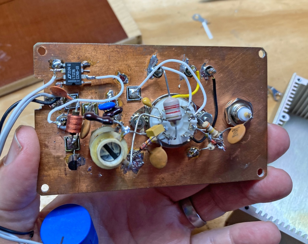
Figure 6. The prototype VFO circuitry. The varactor is the little transistor looking part in the lower left. The precision voltage regulator IC is in the upper left.

Figure 7. The front panel is pretty simple with just the tuning knob and the backlit digital display.
